

Case Studies in the field of in-line inspection
Stay up-to-date and learn more about 3P’s pipeline inspection projects. Our case studies show the close interaction of technology, know-how and experience to keep the operation of pipelines safe and clean, whatever the challenge. The close coordination with our customers on the approach is an important basis for our success.
Here you find a selection of projects with information about the pipeline, the challenge and the target of the inspection. To get more information about our solution concept, our performance and the final result click on the blue button.
Turnkey ILI of a gas storage pipeline
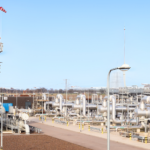
Pipeline Description: The pipeline is a 10” field pipeline connecting an operational site to a cavern at a gas storage
facility in northern Germany. It had never been inspected before, featured a heavy wall thickness, and was temporarily decommissioned for inspection. Why is it challenging? ▪ No Prior Data: The pipeline had never been inspected before, leaving no historical data for reference. ▪ Pipeline Characteristics: The heavy wall thickness required specialized ultrasonic tools for accurate measurements. ▪ Logistical Complexity: Temporary decommissioning and operational takeover added to the complexity of the project. ▪ Tight Schedule: Completing such a comprehensive project within one working week demanded precision and efficiency. Target of the inspection: The primary goal was to assess the pipeline’s integrity and operational safety, identify potential metal loss, and establish a reliable baseline condition. Additionally, precise geographic mapping of welds and anomalies was targeted for better future monitoring and maintenance planning.
Heavy wall MFL – Stretch the boundaries
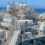
Pipeline Description: Two 10″ heavy wall offshore pipelines running parallel from platform to platform required a metal loss inspection. The length is 1.9 miles (3 km). There are heavy wall riser sections with 0.719″ (18.2mm) wall thickness at the foot of the platforms. The pipelines are located offshore California, USA. Why is it challenging? With common MFL tool designs, the wall thickness of 0.719″ (18.2mm) cannot be sufficiently magnetised in a 10″ pipeline. Therefore, an MFL inspection seemed not feasible. In addition, a previous 3rd party MFL inspection wasn’t successful because of this. Ultrasonic inspection tools failed to get good data because of debris issues. The high cleanliness requirements for UT technology could not be met. Target of the inspection: Perform a high-resolution metal loss inspection for internal and external corrosion. Due to the project circumstances the inspection was to be performed under urgency.
Pre-Commissioning ILI in compressed air
Pipeline Description: Several 36″ pipeline sections in the Canadian Rocky Mountains were in pre-commissioning phase. No permanent traps were built. The total lengths of the sections vary between less than 2km and 16km. The sections had a significant elevation profile. Why is it challenging? The planned products for this pipeline couldn’t be used due to pre-commissioning phase. Hence, an inspection in compressed air was planned. The available compressors were able to provide approximately 10bar (140 PSI) only. In addition, significant elevation profiles in the different sections occurred. Hence, speed excursions and heavy mechanical forces were expected and presented several challenges with regards to ILI tool damages and data quality. Target of the inspection: Perform a high-resolution geometry inspection to detect dents, ID changes and ovalities including a pipeline mapping as part of the acceptance process for the pipeline construction contractors. And to detect pinholes and internal corrosion that are to be expected in this pipeline due to the flood damage as a baseline check for future corrosion growth. assessments.

Turnkey Project – Pumps, Tanks, Traps, Cleaning, Inline Inspections, Drying
Pipeline Description: The challenge is to inspect an onshore hydrogen pipeline that is divided into 4″ and 10″ section, both including some sleeve connections. The age of the sections is 50 and 60 years respectively. The total length is 7.4 km and inline inspection have never been carried out. Why is it challenging? Restricted bore in 4”, unknown bend situations as well as sleeve connections makes this ILI not straight forward. A Turnkey solution was requested, including provision of: Pumps, Storage Tanks, Temporary Traps, Pipeline Cleaning, Intelligent Inline Inspections, Pipeline Drying, Express Data Analysis Reporting. Target of the inspection: Perform high-resolution geometry and metal loss inspections including XYZ measurement.
ILI on Heavy Wall Subsea Pipeline
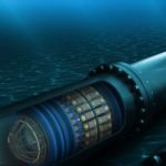
Pipeline Description: Two 18″ looped offshore North Sea wet gas flowlines need to be inspected. The total length is 286Km with up to 27.3mm nominal wall thickness. Potential corrosion had been detected in a previous 3rd party in-line inspection, however the POI was limited and no clear differentiation between corrosion and debris was possible. Hence, the previous inspections were not fully successful, and the data couldn’t be used for a full evaluation of the clients problems. As a consequence, the maximum allowable operational pressure (MAOP) was reduced, clearly affecting the clients production. Why is it challenging? There were many challenging factors like length, wall thickness, urgency, debris history, combination of different sensor technologies, etc. Target of the inspection: Our goal was to perform a custom-made cleaning program to remove the debris prior to the ILI run then perform a high-resolution inspection for internal and external metal loss.

Time is money
Pipeline Description: A European pipeline operator had two 10″ onshore sour gas flowlines which were out of service. Significant corrosion had been detected in a nearby pipeline which supplies the medium for the two 10” pipelines. Hence, it was decided that the operation of the two 10″ pipelines will be stopped to reduce any risk of environmental contamination due to leakages. This inevitably led to a loss of revenues for the pipeline operator. Why is it challenging? There was limited pipeline information available at the time, it was extremely urgent which complicated the tool preparation and due to the known corrosion in the nearby pipeline the pressure was limited to 30 barg. Target of the inspection: Perform a high-resolution inspection for internal and external metal loss. Due to the project circumstances and loss of revenue the inspection was to be performed with utmost urgency, this required many operational, tool preparation and data analysis special procedures. Ultimately, 3P Services determined its express data evaluation service was necessary.:
GEO tool detects mitred bends
Pipeline Description: Product pipelines, diameters 6” to 12”, 12 km long, connecting refinery and tank farm at the harbour. The pipelines pass through a natural reserve. Since adjacent pipelines from another operator had experienced leaks in the natural reserve, the inspection was urgent. Why is it challenging? There are mitred bends present in angles up to approx. 50°. Numbers per line and locations were not known. Target of the inspection Perform a high resolution MFL inspection.
Heavy wall – small diameter ILI
Pipeline Description: Offshore flowlines 4“, wall thickness ½“, designed as a hair pin loop starting from the Gannet A platform (Central North Sea), passing by two subsea production templates and back to Gannet A. The total length is 11.7 km. There are flexible riser sections at the foot of the platform and bend radius of 5D within the risers. Why is it challenging? ½” wall thickness cannot be sufficiently magnetised in a 4” pipeline. Therefore an MFL inspection is not feasible. Ultrasonic inspection tools, that could handle the wall thickness, were not available for 4”. Further, the permanent pig traps, having a length of only 1100mm, cannot be extended. Target of the inspection: Perform a high resolution inspection for internal local corrosion. Due to the project circumstances the inspection was to be performed under urgency.
Bi-Directional MFL application
Pipeline Description: 36” – 9 km long tanker un-loading pipeline, connecting the offshore pipeline end manifold with the tank farm onshore. Why is it challenging? Access to the pipeline is only possible at the onshore end of the pipeline. Target of the inspection Perform a high resolution MFL inspection. As a special issue, study defects in the vicinity of girth welds.

Inspection of a cladded pipe
Pipeline Description: 4” wet sour gas flow line in Northern Germany. Pipe dimensions: carrier pipe, (StE 360.7 S) OD 114,3mm, WT=11mm, ID 86,3mm. Liner is Alloy 825 (material no. 2.4858) WT 3mm. Total length is 600m. Why is it challenging? Ultrasonic inspection tools, that could handle the wall thickness, were not available for 4”. Further, limitations were reported whether the surface between carrier pipe and liner will reflect sufficiently. An MFL inspection is not feasible since it does not refer to the liner material. Further the 11mm ferritic wall thickness cannot be magnetised by a 4” MFL tool. Target of the inspection: Perform a high resolution inspection for liner wall thickness and in particular lift-off of the liner from the internal surface of the carrier pipe.
Lost magnets
Pipeline Description: 5” crude oil pipeline in Northern Germany. Total length is 26km. The pipeline was successfully inspected by 3P Services/MFL already in 1998. What was different? Several years prior to the inspection the client had made mechanical changes (oversized pipe section & valve) at km 5.5 without disclosing this to 3P Services during the inspection planning. During the first attempt to do a follow-up inspection in 2004, this caused damage of the MFL inspection tool. Several magnets were lost in the line and probably broken into pieces when the tool ran over them. Target of the inspection: Recover the magnet pieces from the pipeline as far as possible. Then perform a high resolution MFL inspection.
DMR inspection through cement liner
Pipeline Description: 8” to 14” brine pipelines, Northern Germany, carbon steel pipelines with standard wall thickness (6.3 to 11.0mm). To protect from the corrosive product (saturated NaCl brine), internal cement lining is applied, approx. 4 to 10mm thick. It is known that the cement layer occasionally breaks o ff the internal pipe wall, where the steel surface becomes exposed to the product. Further, cracks may occur in the cement with the same result and potential corrosion underneath the liner. Why is it challenging? An MFL inspection is not feasible since the magnetic field cannot be applied through the cement sufficiently and the sensors cannot get close enough to the pipe wall. UT is prohibited as the sound waves are di ffused inside the cement. Target of the inspection: Determine presence and thickness of the cement liner over length and circumference of the pipeline. Further, identify internal metal loss at spots where the cement is lost and underneath the cement coating.
Inspection of short field lines
Pipeline Description: Field lines connecting well heads and gathering stations within a salt cavern storage facility in Northern Germany. Each wellhead is connected by two pipelines, one to supply solvent water (sea water) and one to dispose brine. All lines are 10” WT 8.0mm, have 1.5D bends and laid underground. Typical length is between 100m and 400m. The project included a total of 12 pipelines. Why is it challenging? There are no permanent pig traps available. Due to the short length of the lines, a conventional MFL inspection was considered to be extremely expensive. From an operational standpoint it was not possible to inspect all lines during one mobilisation. For each well head with two similar lines, one mobilisation was required. Of particular importance was to complete cleaning and inspection in the shortest possible time. Target of the inspection: To perform cleaning runs and execute an MFL inspections at minimum downtime, with an acceptable downtime of 24h for two pipelines.
BIDI riser inspection
Pipeline Description: High pressure gas pipeline, 6” WT 12.7mm, operating pressure 131 bar. Length approx. 10km. The pipeline connects a 20” subsea natural gas transmission line with the Thistle platform in the northern North Sea. It consists of (1) the subsea tee piece with valve station, (2) the sea line and (3) the riser. Why is it challenging? There are no possibilities to install a pig trap at the subsea end of the line. Further, for operational reasons it is not possible to de-pressurise the line. In view to UT-inspections, to flood the riser with water was no option. Target of the inspection: To determine external corrosion on the riser. The riser is located inside a casing that had an unknown history.
BIDI inspection of unloading lines
Pipeline Description: 6″ Jet – A1 & 8″ Gasoline / Gasoil unloading pipelines connecting subsea CBM (Conventional Buoy Mooring System) with onshore storage terminal located in Antalya, Turkey. Water depth at CBM between 12 m – 14 m located in the Mediterranean Sea. The pipeline system has never been inspected before by using high resolution ILI tools. Only very limited pipeline information and drawings were available in preparation of this project. Why is it challenging? There are no possibilities to install pig traps at the subsea end of both pipelines to perform a “standard” uni-directional ILI from trap to trap. Target of the inspection: Determine the presence of internal and external metal loss, geometric anomalies and other features that may affect the pipeline integrity.
BIDI inspection of tanker terminal
Pipeline Description: Three pipelines connect a refinery tank farm on the island of Oahu (Hawaii) with a common pipeline end manifold (PLEM) on the sea bed at a water depth of 30 m (~100 ft). The PLEM is connected with flexible hoses to the single point mooring (SPM) at the surface from where the connection to tankers is made. The pipelines serve for import of crude oil (30”) as well as export of products (16” and 20”). They extend over 1.6 km (~1mls) over land and 2.8 km (~1.8 mls) into the sea to the PLEM. This tanker loading/unloading system has never been inspected before. Why is it challenging? There are no possibilities to install pig traps at the PLEM on the sea bed to perform a “standard” inspection from trap to trap using conventional uni-directional ILI tools. Further, the pipelines have several 1.5D/90° bends and bend combinations on the land section, passing under roads and ditches when passing through a densely developed industrial environment. Target of the inspection: Determine the presence of internal and external metal loss, geometric anomalies and other features that may affect the pipeline integrity.
Subsea launch
Pipeline Description: 36” tanker unloading line connecting a pipeline end manifold (PLEM) in the Atlantic Ocean of the south coast of Spain with a refinery near Huelva, Spain. The line extends over 9 km offshore from the PLEM to shore, then crosses a slim peninsula and then the port entrance of another 1.5 km under river before reaching the refinery territory this line is operated by two different operators. Why is it challenging? Two new sections of the line were constructed by two different contractors: one for the offshore section to the peninsula (conventional offshore lay) and another for the section under the river (horizontal drilling) from the technical point of view of the operator, a bi-directional inspection could not be carries out. As one pipe-laying contractor concluded its part well ahead of the other, 3P’s tools had to be installed into the PLEM long before the tie-in of the two sections on the peninsula was expected. The laying barge had to move on, so the 3P tools had to be in starting position inside the PLEM before it was lowered to the seabed. Therefore, the 3P MFL tools had to cope with a waiting period of unknown duration. Target of the inspection: A profile (gauge plate) run and an MFL baseline survey over the entire pipeline length was contracted to 3P Services. These were part of the acceptance process for the pipeline construction contractors. The inspection had to be done from sea towards land.
Launch from a trap valve
Pipeline Description: 16” – 4058m refined product pipeline connecting an import terminal with a storage depot. Why is it challenging? Various refined hydrocarbon products are imported through this pipeline: JET A-1, diesel, and premium grade gasoline. The pipeline was constructed without consideration for internal pig based inspection. Pigging was foreseen only to permit batching pigs to be launched to separate different products. Batching pigs are launched from a 3-way trap valve. This installation does not allow launch of typical ILI tools. Target of the inspection: High resolution geometric (GEO), mapping (XYZ) and metal loss (MFL) inspection.
BIDI inspection of 3″ gas lift lines
Pipeline Description: 3 x 3” – 9km offshore gas lift loops. Bundled in rigid risers and sea line sections. Flexible jumpers connect the sea lines to risers and well manifold templates. Why is it challenging? Wall thickness is 7.1mm, giving an ID of 74mm. The space available presents an important challenge to construction of a magnetic yoke of sufficient strength. Even more difficult, an earlier profile and gauge run brought out a gauge plate that indicated a reduction of the ID to 58mm. At least one combination of 2.5D back to back bends is present. Although the tool traversing these bends could explain the gauge plate deformation, tool construction and design of the pigging program had to assume that 58mm was the actual minimum bore. Target of the inspection: High resolution geometric (GEO) and metal loss (MFL) inspection.
16″ heavy wall and pipe-in-pipe
Pipeline Description: 16” x 10km looped oil production and produced water reinjection pipeline system. Why is it challenging? Since commissioning in 2008 this pipeline system had never been inspected before. It is difficult to inspect by means of in-line inspection tools due to presence of heavy wall thickness of 25.4mm / 27.94mm (in bends), the 16” / 20” pipe-in-pipe construction and due to no centring spacers installed at regular intervals in the PIP section. Target of the inspection: Determine the current condition and mechanical integrity of the pipeline system regarding metal loss, girth weld anomalies and other features. In addition an XYZ survey was part of the inspection to obtain a vertical profile of the line system and to get geographic coordinates of each girth weld and all other reported features.
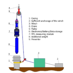
Vertical casing inspection
Pipeline Description: Inspection of 200 m long casings of 12’’ and 20” diameter in an LPG cavern. The cavern is mined into rock that is virtually a solid amorphous mass and is at a depth of almost twice that required to balance the pressure of propane. The static head of the ground water (water table) is greater than that exerted by the stored product thereby preventing outward movement of LPG into the rock. The casings to be inspected have standard wall thickness without any inner diameter changes due to installations or di fferent wall thicknesses and without any noteworthy inclination. Why is it challenging? Vertical Casing inspection is an interesting application as the tools, which are normally applied in horizontal pipelines, must be customised to carry out the inspection vertically. A number of challenges are presented. Since the tools are fed into the casing by gravity, they must allow for the friction of passing through the pipe at the same time presenting the inspection sensor arrays as close as possible to the pipe wall. Transition from air/gas phase into water meant that buoyancy was also be considered. Target of the inspection: In common with pipeline inspection, the objective in casing inspection is to achieve a high resolution data set about metal loss and girth welds to confirm casing integrity. Minimising costs since neither workover nor logging units are required.
BIDI MFL for large diameter tank farm lines
Pipeline Description: 34” and 42” depot lines connecting manifolds with the storage tanks. In the world of hydrocarbon transportation by pipeline, depot lines, jetty lines, lateral lines and others were often constructed without consideration for the usage of in-line inspection tools. Especially older lines may be affected due to different codes for design and older regulations. These lines pose significant challenges for today’s operators and ILI firms to achieve effective, high resolution internal inspections. Why is it challenging? The lines were constructed without consideration for internal inspection with ILI tools. A number of features pose obstacles to pigging: No launcher/receiver traps installed;
1.5D back to back bends; no possibility to have a trap at the manifold end; reduced bore gate valves. Target of the inspection: Determine the integrity of the lines, wall thickness measurement and internal metal loss and other features.
Support to locate internal local metal loss
Pipeline Description: 6” crude oil gathering pipeline in the area of Gainsborough, Lincolnshire, UK.
The pipeline is 2.1km long and was built in 1985. 3P had done an ILI using GEO and MFL technology. The client
required the results urgently. A preliminary report with geometric and metal loss results was provided 24 hours
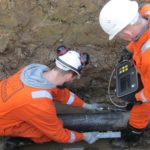
after the conclusion of the pigging operations. The pipeline was reported to have an internal 6 o’clock metal loss issue over some sections. Typically, the features were extremely small by length and width in an otherwise unaffected wall. The depth of these pit and pinhole type features was significant in some cases. The client started a repair campaign without delay. Target of this campaign was to do local repairs on features exceeding a certain ERF value. Why was special? On day 3 after the ILI conclusion, the client called 3P and explained that the major reported features of internal metal loss in the first two repair locations could not be confirmed by UT inspectors on site. The locations were confirmed to be correct in relation to the dig-up sheets provided by 3P and reference to nearby installations (significant spools, bends, etc). The client’s contractors were on site on stand-by and 3P’s advice was required immediately. Target of the inspection: 3P Services offered to deploy our HandyScan scanning device to guide the UT inspectors to the precise locations of the features at the external surface of the pipe.
BIDI inspection of tanker unloading line with MFL UT Combo
Pipeline Description: The pipeline connects a crude oil tank farm in India with a common pipeline end manifold (PLEM) on the sea bed at a water depth of approx. 35 – 40 m. The PLEM is connected with flexible hoses to the single point mooring (SPM) from where the connection to tankers is made. The pipeline serve for import of crude oil. It extends over 9 km over land and 10 km into the sea. This tanker unloading system has never been inspected before. Why is it challenging? There are no possibilities to install a pig trap at the PLEM on the sea bed to perform a “standard” inspection from trap to trap using conventional uni-directional ILI tools. Further, the pipelines have several 3D/90° bends on the land section during passing under roads and through an industrial environment. Target of the inspection: Determine the presence of internal and external metal loss by using the benefits of both technologies (MFL and UT). Additionally, finding of geometric anomalies and other features that may affect the pipeline integrity. Also, determination of the pipeline route with an XYZ module.